I remember when I first started taking Networking classes and was introduced to the OSI Model. I will be perfectly honest, I was not a fan. To me, it seemed like some abstract concepts of how computers communicate. I thought it would never be useful to me. However, I can say that I continue to use it quite often. It really is a great concept and tool to understand when you are troubleshooting.
What is the OSI Model?
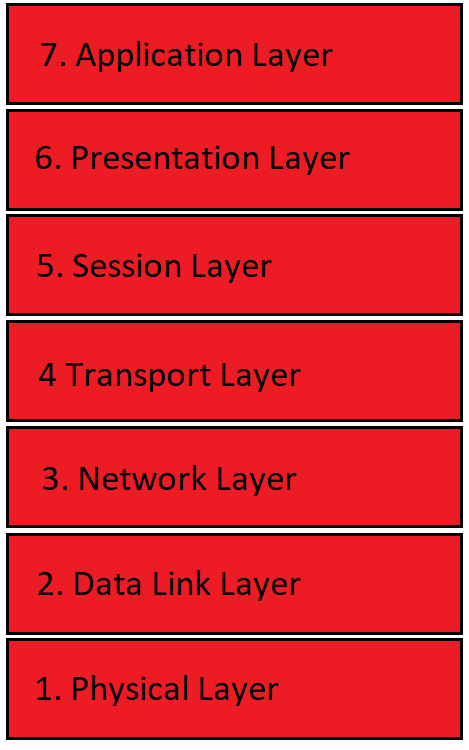
So what is the OSI Model? The OSI Model is a conceptual model that standardizes communication functions. This model is not specific to any particular hardware or technology. The OSI Model is represented in an image like this one:
Why is the OSI Model Important?
This model is important to understand for any Network or System Administrator. Since it is vendor-agnostic you can apply it to almost any situation. All equipment that communicates over a network conceptually uses this model for their communication. Having a good understanding of it will help you troubleshoot problems. As we go further into this post it will become more clear.
Physical Layer – Layer 1
Starting from the bottom and working our way up we have layer 1 which is the physical layer. This layer handles the actual signal going across the wire. It receives different types of signals or transmits them. This can be anything from electrical to fiber optic to radio frequencies. It even is where we define wiring pinouts such as spec A and spec B for Cat5e and Cat 6 wiring.
At this layer of the OSI Model, we convert digital bits into whatever signal we will be using for transmission. We will also receive that signal and convert it into digital bits.
In regards to a specific device, you can think of a computers network or wireless card as working at the Physical Layer. It converts digital bits into an electrical signal to be carried across the network cable. The on the other end it converts the electrical signal back into digital bits.
Data Link Layer – Layer 2
The next layer as we move up is the Data Link layer. The data link layer is responsible for node to node data transfer. This is typically where your network switches work at, which we will discuss in another post. The IEEE 802 standards for networking also work at the Data Link layer. You may be familiar with 802.3 for ethernet or 802.11 for wireless standards.
The Data Link layer is actually broken down into two sub-layers. This first being the MAC or Media Access Control layer. This layer specifies how devices gain access to a transfer medium at layer 1. The second is the LLC or Logical Link Control layer. This layer is about encapsulating network-layer protocols. We will go over encapsulation a little bit further in this post.
Network Layer – Layer 3
This is the layer where I started to understand the OSI Model. The network layer is where we start seeing IP addresses. This is the layer where routers typically work and some Layer 3 switches. This layer is the mechanism to route packets between networks. When we talk about how different networking equipment works this will all make much more sense.
Delivery at the network layer is not always guaranteed but there are ways we can help with this. We will go over those at the next layer.
Transport Layer – Layer 4
The transport layer is where we start to see the inclusion of TCP and UDP ports. Remember in the previous layer I mentioned delivery is not always guaranteed. This is where TCP and UDP come into play.
TCP
TCP which stands for Transmission Control Protocol. This protocol allows two machines to exchange a stream of data. TCP, however, does validation to confirm that the data it sent reaches its destination. It does this by only sending some of the packets and waits for the remote end to request the next.
An example of a TCP stream could be the server says “here is packets 1,2,3,4” to the client. The client then responds with “Ok please send me packet 5”. Now let’s say the server says “here is packets 1,2,3,4” and for some reason packet, 4 never arrived at the client. The client would then say “Ok please send me packet 4” and the server will resend packet 4 along with a few more packets. This is how TCP creates reliable connections. However, these reliable connections come at a cost of overhead. Because the traffic is reliable it is slower to reach its destination in full. So it isn’t good for applications like VoIP or streaming video.
UDP
UDP or User Datagram Protocol is the other protocol at the Transport Layer in the OSI Model. The real difference here is that the transmission is not guaranteed. With UDP the server will send a stream of data and if any packets are dropped before reaching the client they are lost. These lost packets are typically corrected within the application.
UDP is a better protocol to use when you need as close to real-time transmission as possible. So for applications like Skype that uses voice and video.
At the Transport Layer of the OSI Model, we also start to see the concept of ports. Servers typically have 1 IP address and different applications listen on different ports. This helps the server to differentiate the traffic it is receiving.
We are all familiar with ports 80 and 443. Those are the ports of typical web traffic. So web servers on the internet are listening on port 80 and 443 for web traffic. When they receive that traffic it is sent to the specific application that is listening.
Session Layer – Layer 5
This layer controls the communication between two devices. It is responsible for setup and teardown of that communication. It also controls the duplex of a network connection, whether it is half-duplex or full-duplex. This layer will also help to mask any errors or problems from the higher layers.
Presentation Layer – Layer 6
The Presentation Layer of the OSI Model is responsible for transforming the data into a format the Application Layer can accept. One example of this is encryption and decryption which typically happens at the presentation layer.
Another way to think of the presentation layer is where ASCII characters get converted to binary and vice versa.
Application Layer – Layer 7
The last but certainly not least is Layer 7 the Application Layer of the OSI Model. The best way to think of the Application layer is what the user interacts with. So your Web Browser, Word Processor and Email applications all sit at the Application Layer. This layer is really what your everyday user sees when they are using a computer.
Other Notes about the OSI Model
How does traffic flow
Traffic from one computer to another flows through all layers of the OSI model. Let’s try and do a quick example.
User A wants to FTP a file to User B across the network. User A fires up his FTP client which is at the application layer and initiates a transfer to User B. The information from the Application layer get converted to binary at the presentation layer. Then the Session layer starts to work on establishing the connection to User B. The Transport layer determines that it will use TCP and port 21 which is the port for FTP. The traffic then gets sent to the network layer where it determines how the traffic is going to get to its destination. Next, we go through the Data Link Layer where the traffic is going out based on the MAC address. Lastly, we hit the physical layer where all the data is converted to an electrical signal to be sent across the wire to User B.
Encapsulation
As we go through each layer our traffic gets encapsulated by each layer of the OSI Model. Encapsulation is just where each layer adds its own headers to the traffic to specify certain attributes of the traffic. Once our example FTP traffic reaches User B’s computer we go through the entire process in reverse. Each layer un-encapsulating it’s part of the traffic until it reaches User B’s FTP server at the Application layer.
How do you remember the OSI Model
Remembering the OSI Model was one of the biggest challenges I faced in networking classes. It really was just straight memorization. Luckily a quick google search will pop up millions of resources on the OSI Model. But if you really want to memorize it there is a great acronym I used to help me. Now I did not make this up so I shouldn’t get any credit for it.
“All People Seem To Need Data Processing”
This acronym starts at Layer 7 and goes to Layer 1. If you prefer one that goes the other way around I would recommend:
“Please Do Not Throw Sausage Pizza Away”
This acronym starts with Layer 1 and goes to Layer 1. Whichever one works better for you I would say stick with it.
Conclusion
The OSI Model seems in school like one of those things you have to memorize but will never benefit you. I certainly felt that way but learning it did give me a better understanding of computer to computer communication. I also find my self thinking about it when I am troubleshooting a networking problem.
If you found this article helpful check out my Systems Administration 101 guide as well as my Networking Basics page.